Automated Drone Charging

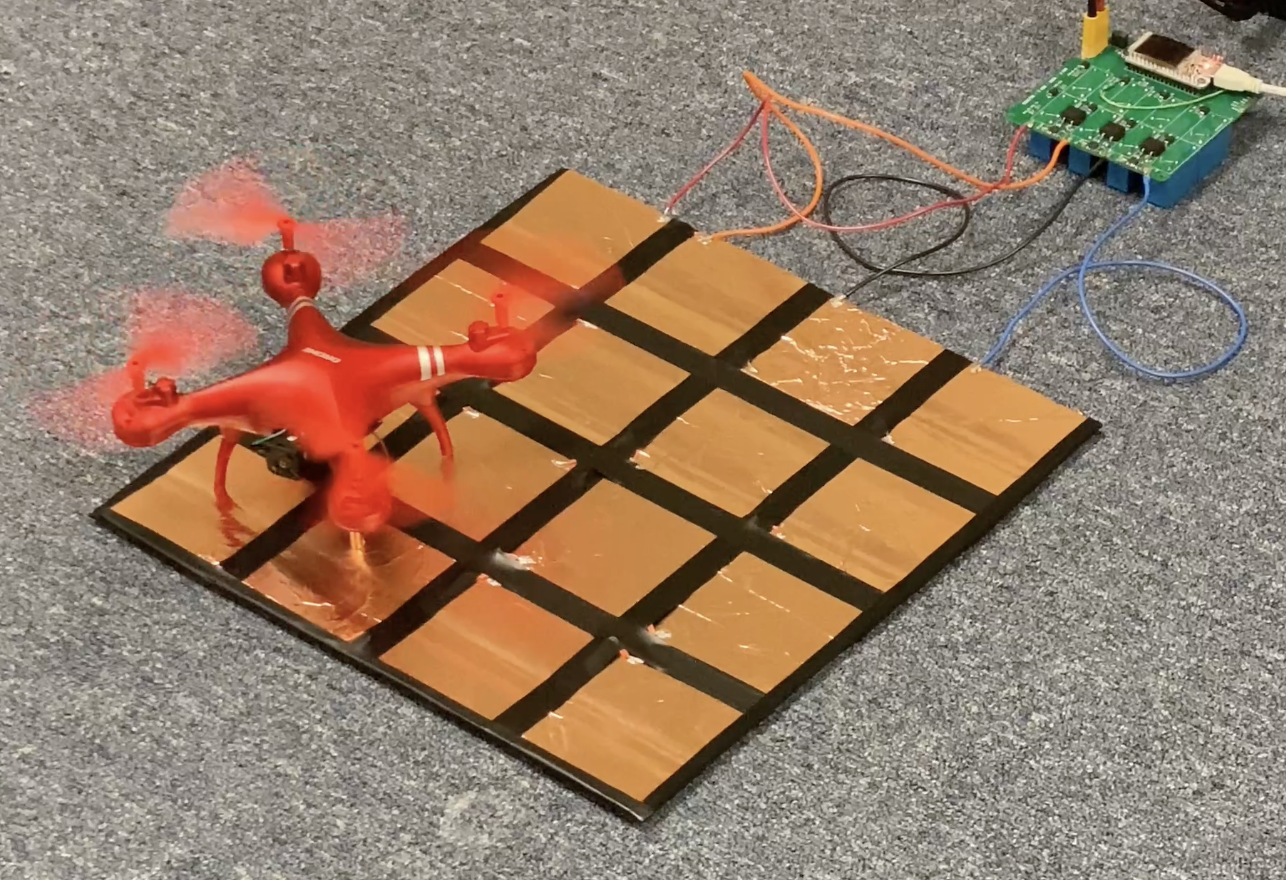
One of the biggest challenges preventing drones from autonomously operating 24/7 is the need to either swap or charge batteries. Either method can be a multi-step process requiring large amounts of mechanical precision. I spent part of my 10 week internship at HBOI researching, designing, and prototyping a charging concept that could work without human intervention. The following prototype aimed to alleviate the mechanical precision required to connect a charger to a drone battery. Instead of relying on a physical connector plugging into a battery, the following charging pad can route the battery terminals to a charger as long as a drone can land in the arbitrarily large pad.
Drone
An automated charging solution will be the most effective if the majority of the added components and complexity are on the charging side rather than the drone side. This keeps additional weight off of the drone and allows the charging concept to work with a potentially wide variety of drones.
The main modification to the drone requires the terminals of the battery to be routed to the landing gear of the drone. In the most simple configuration, there needs to be two physical contact points: one for the positive lead of the battery and the other for the negative lead.

Landing Pad
The landing pad is responsible for bridging the charging terminals of the drone to the controller board. The landing pad is also kept as simple as possible to allow the size of the pad to be easily scaled without added complexity or cost.
The landing pad is made out of copper tape cut into squares and attached to a cardboard sheet. The copper squares that are the same color in the following image are electrically connected. The size of the copper squares and the arrangement of the colors ensure that the positive and negative leads from the drone will come into contact with different colored squares: preventing the contacts from ever short circuiting. My prototype consisted of 16 squares in total (4 squares of each color electrically connected together), however, any multiple of 4 squares will work.

Controller
The controller is responsible for routing the positive and negative charging leads to the copper squares that are in contact with the positive and negative leads of the drone’s battery. Because the drone can land in any orientation on the charging pad, the controller has to sense what color copper square is connected to what lead of the drone’s battery.

Sensing Logic
The controller uses three bi-directional current sensors to determine the location of the battery terminals (i.e. what color square they landed on). On the controller board itself, the four uniquely colored squares are connected together as shown below with a resistor in series with a current sensor. As soon as the drone lands, a small current will flow from the positive side of the battery to the negative side through at least one current sensor. Depending on which current sensor is reading a positive, negative, or null current value, the controller can determine which lead of the battery is connected to which colored square on the landing pad. After the orientation is established, the controller, using an array of relays, can direct the positive and negative leads of the charger to the the positive and negative leads of the battery and initiate charging.

Circuit Design
I was able to build this prototype by designing a custom circuit board in KiCad that held all of the sensing logic and relays used to route the battery terminals to the charging terminals. Besides the sensing and switching logic, the circuit was controlled by an ESP32 breakout board.

Thoughts
I was able to successfully use the prototype to charge the single-celled drone shown in the first image. In order to turn the prototype into a functioning system that can work reliably, the following issues would need to be addressed:
- The border between the squares on the landing pad needs to be as small as possible to prevent the contacts on the drone from landing in between squares and failing to establish an electrical connection with the pad. However, the border should also be kept large enough to prevent accidental short circuits between pads of different colors.
- For use in outdoor locations, an alternative to copper should be used for the landing pad to prevent corrosion (looking into using niobium …).
- As a safety issue, the terminals of the battery should not be constantly exposed on the landing gear of the drone. A mechanism (either mechanical or electrical) needs to be implemented to prevent accidental current flow from these terminals when the drone is not charging.